
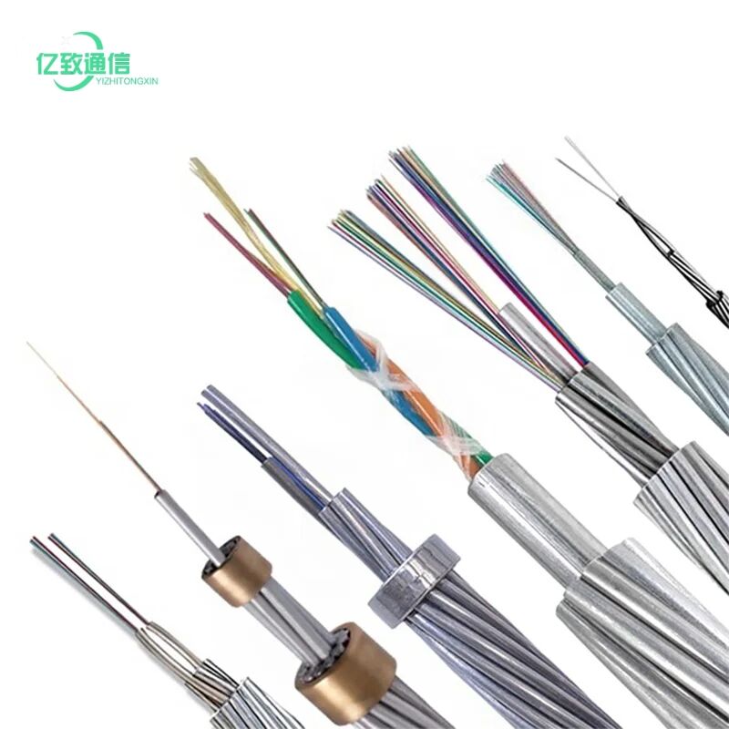
Fiber-to-the-Home (FTTH) networks have revolutionized telecommunications infrastructure, bringing high-speed internet directly to residential and commercial properties. At the heart of these networks lies a critical component that determines signal distribution efficiency and network performance: the PLC splitter. Understanding how to select the appropriate PLC splitter ratio is fundamental for network engineers, telecommunications providers, and infrastructure planners who aim to optimize their FTTH deployments while maintaining cost-effectiveness and signal integrity.
The selection process for PLC splitter ratios involves multiple technical considerations that directly impact network performance, subscriber capacity, and long-term scalability. Modern FTTH architectures rely heavily on passive optical splitters to distribute optical signals from central offices to multiple end users efficiently. These devices enable service providers to maximize their fiber infrastructure investments while delivering consistent service quality across diverse geographical areas and subscriber densities.
Network topology requirements, subscriber distribution patterns, and future expansion plans all play crucial roles in determining the optimal PLC splitter configuration. The complexity of these decisions increases when considering factors such as optical power budgets, insertion losses, and the need for flexible network architectures that can adapt to changing market demands and technological advancements in the telecommunications industry.
Understanding PLC Splitter Fundamentals
Basic Operating Principles
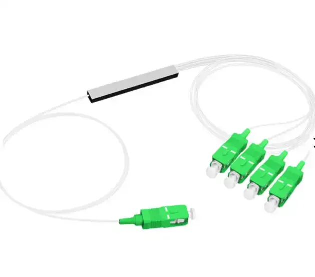
PLC splitter technology operates on the principle of optical waveguide splitting, where a single input optical signal is divided into multiple output signals through carefully engineered planar lightwave circuits. These devices utilize silicon-based photonic integrated circuits that provide precise control over optical power distribution across multiple output ports. The manufacturing process involves photolithography techniques similar to semiconductor fabrication, ensuring consistent performance characteristics and reliable long-term operation in demanding field environments.
The core functionality of a PLC splitter relies on evanescent wave coupling within the waveguide structure, allowing controlled power transfer between adjacent optical paths. This approach provides superior wavelength independence compared to traditional fused biconic taper splitters, making PLC technology particularly suitable for wavelength division multiplexing applications and future-proof network designs.
Key Performance Metrics
Insertion loss represents the most critical performance parameter for any PLC splitter, directly affecting the optical power budget available for signal transmission over extended fiber distances. Typical insertion loss values vary depending on the split ratio, with 1x2 splitters exhibiting approximately 3.5 dB loss, while 1x32 configurations may introduce up to 17.5 dB of insertion loss under ideal conditions.
Uniformity specifications ensure balanced power distribution across all output ports, preventing service quality variations between different subscribers connected to the same splitter. Modern PLC splitter designs achieve uniformity values better than ±0.8 dB, ensuring consistent signal levels regardless of the specific output port assignment for individual subscribers.
Analyzing Network Architecture Requirements
Centralized versus Distributed Splitting Strategies
Centralized splitting architectures concentrate all PLC splitter devices at central office locations or primary distribution points, providing simplified network management and easier maintenance access. This approach typically employs higher split ratios, such as 1x64 or 1x128, to maximize the number of subscribers served from a single fiber feeder. However, centralized designs require careful consideration of optical power budgets and may necessitate optical amplification for extended reach applications.
Distributed splitting strategies deploy PLC splitter units at various points throughout the outside plant infrastructure, including fiber distribution hubs and neighborhood access points. This methodology often utilizes cascaded splitting configurations, combining different split ratios to achieve optimal power distribution and network flexibility while minimizing individual splitter insertion losses.
Subscriber Density Considerations
Rural deployment scenarios typically require different PLC splitter strategies compared to dense urban environments due to varying subscriber concentrations and geographical constraints. Lower split ratios, such as 1x4 or 1x8, may prove more economical in sparsely populated areas where fiber resources are abundant relative to subscriber demand, allowing for future growth without immediate infrastructure changes.
Urban high-density deployments often justify higher split ratios to maximize fiber utilization efficiency and reduce per-subscriber infrastructure costs. Multi-dwelling unit applications may benefit from 1x32 or 1x64 PLC splitter configurations, particularly when combined with appropriate fiber management systems and optical power budgeting strategies.
Optical Power Budget Calculations
System Loss Analysis
Comprehensive optical power budget analysis must account for all sources of signal attenuation throughout the entire FTTH transmission path, including fiber attenuation, connector losses, splice losses, and PLC splitter insertion losses. Standard single-mode fiber exhibits attenuation coefficients of approximately 0.35 dB/km at 1310 nm and 0.25 dB/km at 1550 nm wavelengths, values that accumulate significantly over extended transmission distances common in FTTH networks.
Connector and splice losses contribute additional attenuation that varies depending on installation quality and environmental conditions. Typical fusion splice losses range from 0.02 to 0.05 dB per splice point, while mechanical connectors may introduce 0.3 to 0.5 dB of additional loss per connection interface throughout the optical path.
Margin Requirements and Safety Factors
Industry best practices recommend maintaining optical power margins of 3 to 5 dB above minimum receiver sensitivity levels to accommodate component aging, environmental variations, and potential network reconfigurations. These safety margins become particularly critical in PLC splitter applications where high split ratios result in significant optical power division among multiple output ports.
Temperature variations can affect PLC splitter performance characteristics, with insertion loss variations of ±0.5 dB typical across operating temperature ranges from -40°C to +85°C. Environmental protection strategies and proper component specification ensure reliable network operation under diverse climatic conditions encountered in outside plant installations.
Split Ratio Selection Strategies
Common Split Ratio Applications
The 1x2 PLC splitter configuration provides the lowest insertion loss option for applications requiring simple point-to-point signal duplication or network redundancy implementations. These devices find particular utility in business service applications where high optical power levels are essential for extended transmission distances or high-bandwidth service requirements that demand maximum signal integrity.
Medium split ratios, including 1x4, 1x8, and 1x16 configurations, offer balanced performance characteristics suitable for neighborhood-level distribution applications. These PLC splitter options provide reasonable insertion loss values while supporting sufficient subscriber counts for typical residential cluster deployments, making them popular choices for suburban FTTH network architectures.
High Split Ratio Considerations
The 1x32 PLC splitter represents a common choice for high-density applications where fiber conservation is paramount, such as multi-tenant buildings or urban residential developments. While insertion loss values approach 17 dB, careful optical power budgeting can accommodate these levels when combined with appropriate transmitter power levels and sensitive receiver designs.
Ultra-high split ratios, including 1x64 and 1x128 PLC splitter configurations, push the boundaries of passive optical network design and typically require specialized consideration of component specifications and network architecture. These applications may benefit from optical amplification or advanced modulation techniques to maintain adequate signal quality across all subscriber connections.
Installation and Deployment Considerations
Environmental Protection Requirements
Outdoor PLC splitter installations demand robust environmental protection to ensure reliable long-term operation in challenging weather conditions and temperature extremes. Sealed enclosure designs with appropriate IP67 or IP68 ratings provide necessary moisture protection, while UV-resistant materials prevent degradation from prolonged sunlight exposure in aerial installation environments.
Underground installations require additional consideration of soil conditions, groundwater levels, and potential mechanical stresses from soil movement or construction activities. Proper cable management and strain relief techniques protect PLC splitter connections from damage during installation and subsequent maintenance activities throughout the network lifecycle.
Maintenance and Troubleshooting Access
Strategic placement of PLC splitter devices must balance network performance optimization with practical maintenance accessibility requirements. Centralized locations may simplify troubleshooting procedures but can create single points of failure that affect multiple subscribers simultaneously, while distributed architectures provide better fault isolation capabilities at the expense of increased maintenance complexity.
Documentation and labeling systems become critical for networks utilizing multiple PLC splitter configurations and split ratios throughout the service area. Clear identification of splitter types, port assignments, and optical power levels enables efficient troubleshooting and network optimization activities while supporting future expansion and reconfiguration requirements.
Future-Proofing Network Designs
Scalability Planning
Effective PLC splitter selection must anticipate future subscriber growth patterns and bandwidth demand evolution to avoid premature network obsolescence or costly infrastructure replacements. Modular splitter designs and flexible enclosure systems enable incremental capacity additions without disrupting existing service delivery, supporting organic network growth strategies that align capital expenditures with revenue generation.
Technology evolution considerations include potential migration to higher-speed PON standards, advanced wavelength division multiplexing implementations, and emerging optical networking technologies that may require different optical power budget allocations or signal quality requirements compared to current-generation systems.
Economic Optimization Strategies
Life-cycle cost analysis should encompass initial PLC splitter procurement costs, installation expenses, ongoing maintenance requirements, and potential upgrade costs associated with different split ratio selection strategies. Higher split ratios may reduce initial fiber infrastructure costs but could limit future flexibility or require earlier replacement to support advanced services or increased subscriber demands.
Standardization benefits emerge from consistent PLC splitter specifications across network deployments, reducing spare parts inventory requirements, simplifying technician training programs, and enabling bulk procurement advantages that can significantly impact overall network economics while maintaining operational efficiency.
FAQ
What factors determine the optimal PLC splitter ratio for my FTTH network
The optimal PLC splitter ratio depends on several key factors including subscriber density, available optical power budget, transmission distance requirements, and future growth projections. Network topology preferences, whether centralized or distributed splitting, also influence the selection process. Consider your specific deployment environment, maintenance accessibility needs, and economic constraints when evaluating different split ratio options. Rural areas with lower subscriber density may benefit from lower split ratios like 1x4 or 1x8, while urban high-density deployments often justify 1x32 or higher configurations to maximize fiber utilization efficiency.
How does PLC splitter insertion loss affect network performance
PLC splitter insertion loss directly impacts the optical power budget available for signal transmission, affecting maximum transmission distances and service quality margins. Higher split ratios introduce greater insertion loss, with 1x2 splitters typically exhibiting 3.5 dB loss compared to 17+ dB for 1x32 configurations. This loss must be carefully balanced against other system losses including fiber attenuation, connector losses, and required safety margins. Proper optical power budgeting ensures adequate signal levels reach all subscribers while maintaining sufficient margin for component aging and environmental variations throughout the network lifecycle.
Can different PLC splitter ratios be mixed within the same network
Yes, different PLC splitter ratios can be strategically mixed within the same FTTH network to optimize performance and cost-effectiveness for varying deployment scenarios. This approach allows network designers to match splitter specifications to local requirements, using lower ratios in areas with challenging optical budgets and higher ratios where conditions permit. However, mixing different ratios requires careful documentation, standardized maintenance procedures, and consideration of spare parts inventory management. Cascaded splitting strategies often employ multiple splitter stages with different ratios to achieve optimal power distribution while maintaining network flexibility and operational efficiency.
What are the key differences between PLC splitters and fused biconical taper splitters
PLC splitter technology offers superior wavelength independence, better uniformity across output ports, and more consistent performance characteristics compared to traditional fused biconical taper (FBT) splitters. PLC devices utilize semiconductor fabrication techniques that provide precise control over optical characteristics, while FBT splitters rely on mechanical fiber manipulation processes that can introduce performance variations. PLC splitters also support higher split ratios more effectively and demonstrate better long-term stability in challenging environmental conditions. However, FBT splitters may offer cost advantages for simple low-ratio applications, making the choice dependent on specific network requirements, performance specifications, and economic considerations for each deployment scenario.